


CCD Camera BGA Rework Station
Safe, precision rework for SMD, BGA, and LED chips. The DH-A2 rework station combines precision, reliability, and affordability in an all-in-one solution for all your rework needs, from complex, densely populated PCBAs to simple LED strips. Yet it remains easy to learn and use, enabling technicians to quickly and confidently master precision alignment, delicate placement, and precise heating control.
الوصف
CCD Camera BGA Rework Station
1.Application of CCD Camera BGA Rework Station
Motherboard of computer, smart phone, laptop, MacBook logic board,digital camera ,air conditioner, TV and other
electronic equipments from medical industry, communication industry, automobile industry, etc.
Suitable for different kind of chips: BGA,PGA,POP,BQFP,QFN,SOT223,PLCC,TQFP,TDFN,TSOP,PBGA,CPGA,LED chip.
2.Product Features of CCD Camera BGA Rework Station
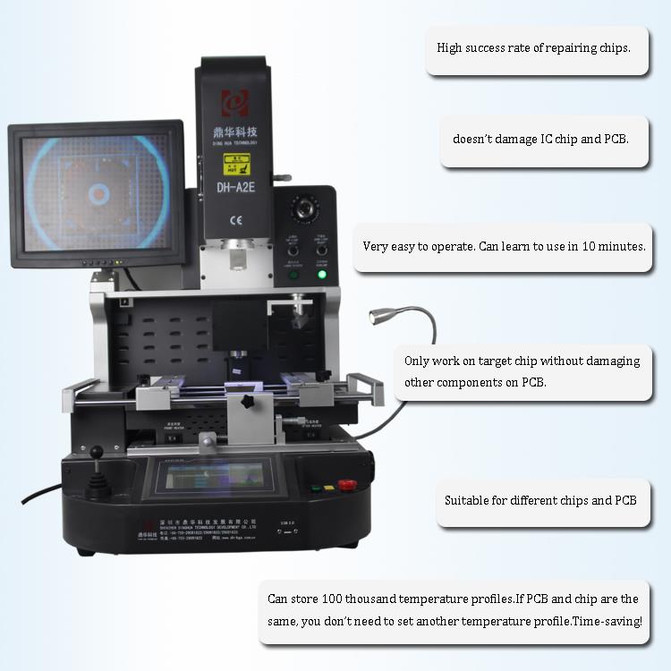
•The only SMT rework station in its price range to include true high-definition (HD) vision on par with the industry’s
most advanced rework systems, the RW1210 provides a crystal-clear superimposed image of the component leads
and the PCB solder pads, even at 230X zoom.
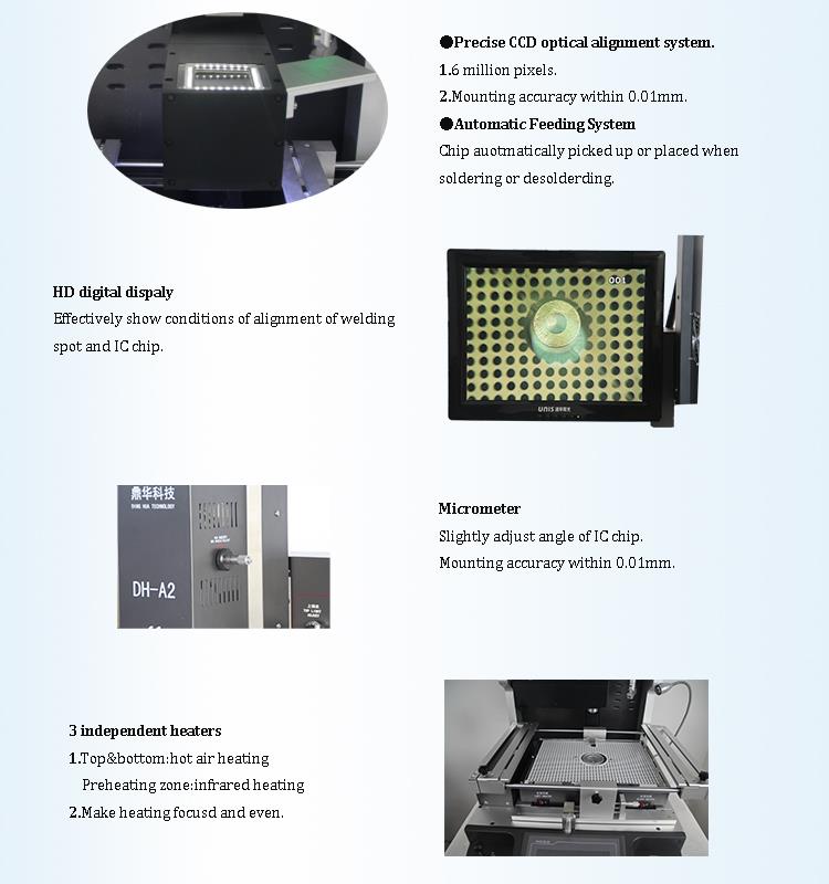
This is thanks to a combination of its 1.3 million pixel, split-vision CCD camera and high-brightness, independently
controlled lighting for both the component and the PCB. Regardless of component pitch or size, your rework techn-
ician will have no trouble seeing when they’ve achieved perfect alignment on the system’s 15” display.
•The DH-A2E rework station has two hot air heaters, one top and one bottom, for fully controllable desoldering and
resoldering that provides solid results without shifting even the smallest components. For preheating, the bottom hot
air heater is surrounded by a 2700W “Rapid IR” underheater. This 350 mm x 250 mm (13.75” x 10”) IR preheater gently
raises the temperature of the PC or LED substrate to prevent warpage and reduce stress on the
components and solder joints adjacent to the rework site. The infrared heaters are fully enclosed in a glass-shielded
compartment that quickly dissipates heat and prevents debris from falling into the elements, ensuring operator safety,
reduced maintenance, and easy
cleaning.
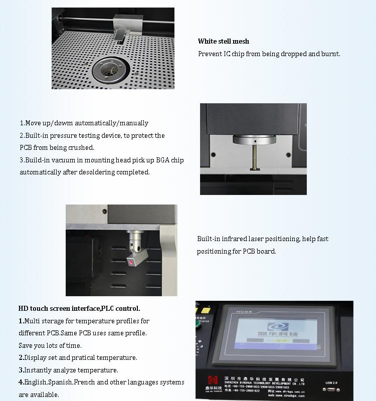
•Precise temperature control can be ensured with 3 independent heating areas. The machine can set and save 1 million
of temperature profile.
• Build-in vacuum in mounting head pick up BGA chip automatically after desoldering completed.
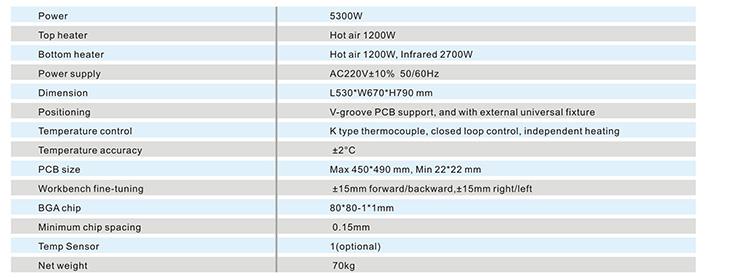
3.Specification of CCD Camera BGA Rework Station
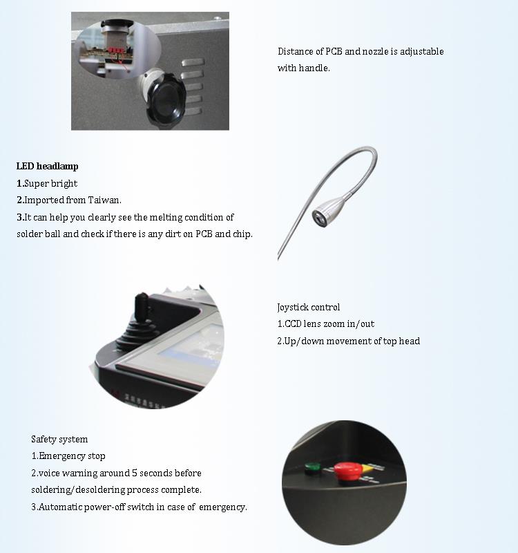
4.Details of CCD Camera BGA Rework Station
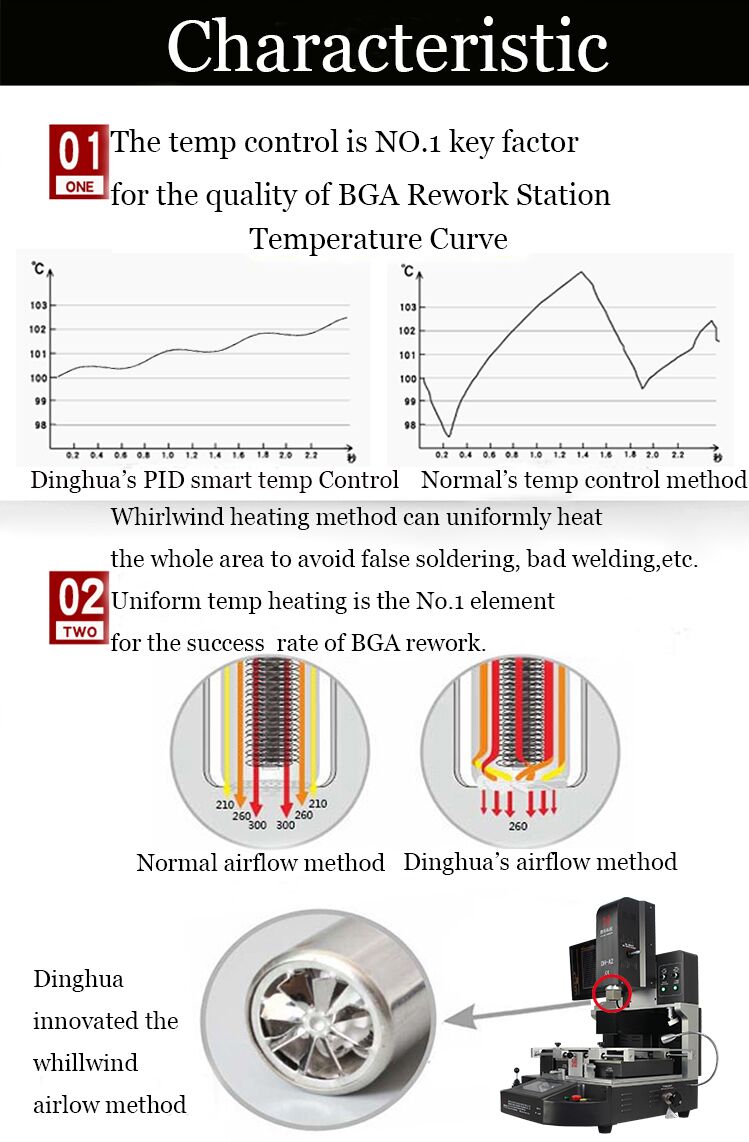
5.Why Choose Our CCD Camera BGA Rework Station?

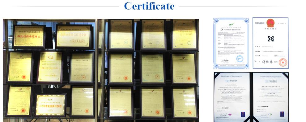
6.Certificate of CCD Camera BGA Rework Station
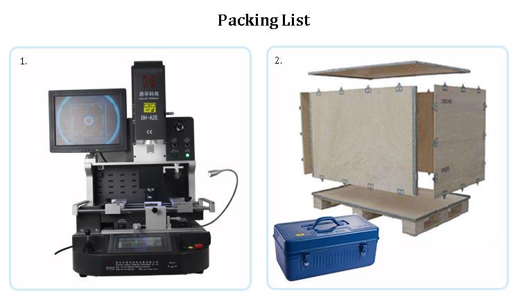
7.Packing & Shipment of CCD Camera BGA Rework Station
8.FAQ
What are BGA rework station usage and skills?
Desoldering.
Preparation for rework: Determine the nozzle to be used for the BGA chip to be repaired.The temperature of the repair is
determined according to the leaded and lead-free solder used by the customer, because the melting point of the lead solder
ball is generally 183 ° C, and the melting point of the lead-free solder ball is generally about 217 ° C.Fix the PCB board on the
BGA rework platform, and the laser red dot is positioned at the center of the BGA chip. Shake the placement head to determine
the placement height.
2. Set the desoldering temperature and store it for later rework, you can call it directly. In general, the temperature of desold-
ering and soldering can be set to the same group.
3. Switch to the removal mode on the touch screen interface, click the repair button, the heating head will automatically heat
down the BGA chip.
4. Five seconds before the temperature is over, the machine will give an alarm and send a drop of sound. After the temperature
curve is over, the nozzle will automatically pick up the BGA chip, and then the head will suck the BGA up to the initial position.
The operator can connect the BGA chip with the material box. The desoldering is completed.
Placement soldering.
After the tin is completed on the pad, use a new BGA chip or a BGA chip that has been implanted. Secure the PCB board.
Place the BGA to be soldered approximately at the pad location.
2. Switch to the placement mode, click the start button, the placement head will move down, and the nozzle automatically picks
up the BGA chip to the initial position.
3. Open the optical alignment lens, adjust the micrometer, the X-axis Y-axis to adjust the front and rear of the PCB board, and the
R angle to adjust the angle of the BGA. The solder balls on the BGA (blue) and the solder joints on the pads (yellow) can be display-
ed in different colors on the display. After adjusting to the solder ball and the solder joints completely, click the “Alignment Complete”
button on the touch screen.The placement head will automatically drop, put the BGA on the pad, automatically turn off the vacuum,
then the mouth will automatically rise 2~3mm, then heat. When the temperature curve is over, the heating head will automatically
rise to the initial position. The
welding is completed.


